Difference between revisions of "Tools"
Jump to navigation
Jump to search
| (5 intermediate revisions by 2 users not shown) | |||
| Line 44: | Line 44: | ||
}} | }} | ||
{{ToolInfo | {{ToolInfo | ||
| − | |||
| − | |||
| − | |||
| − | |||
| − | |||
| − | |||
|DC Power Supply | |DC Power Supply | ||
|A desktop device to provide DC power to a circuit at a specified voltage. Our BK Precision power supplies have three outputs: two output 0-24 V variable voltage with a max current of .5 A, and one outputs a fixed 5 V with a max current of 4 A. The electronics station in the center of the Maker Hub has several power supplies available for use. If all of these are in use, or if you would like to use a power supply elsewhere in the Hub, you can check one out from the Tool Room. | |A desktop device to provide DC power to a circuit at a specified voltage. Our BK Precision power supplies have three outputs: two output 0-24 V variable voltage with a max current of .5 A, and one outputs a fixed 5 V with a max current of 4 A. The electronics station in the center of the Maker Hub has several power supplies available for use. If all of these are in use, or if you would like to use a power supply elsewhere in the Hub, you can check one out from the Tool Room. | ||
|[[File:DC Power SupplyDC PS.jpg|100px|center]] | |[[File:DC Power SupplyDC PS.jpg|100px|center]] | ||
|Electronic Devices | |Electronic Devices | ||
| − | }} | + | }} |
{{ToolInfo | {{ToolInfo | ||
|Handheld Multimeter | |Handheld Multimeter | ||
| Line 61: | Line 55: | ||
|Electronic Devices | |Electronic Devices | ||
}} | }} | ||
| − | + | {{ToolInfo | |
|Oscilloscope | |Oscilloscope | ||
|An instrument for measuring and graphically displaying varying signal voltages. They can can plot a changing electrical signal over time, and then analyze it for properties including frequency, wavelength, and amplitude. Our oscilloscopes have four channels, meaning they can display four signals at once. | |An instrument for measuring and graphically displaying varying signal voltages. They can can plot a changing electrical signal over time, and then analyze it for properties including frequency, wavelength, and amplitude. Our oscilloscopes have four channels, meaning they can display four signals at once. | ||
| Line 72: | Line 66: | ||
|[[File:FunctionGeneratorFG.jpg|100px|center]] | |[[File:FunctionGeneratorFG.jpg|100px|center]] | ||
|Electronic Devices | |Electronic Devices | ||
| − | }} | + | }} |
{{ToolInfo | {{ToolInfo | ||
|Soldering Iron | |Soldering Iron | ||
| Line 189: | Line 183: | ||
{{ToolInfo | {{ToolInfo | ||
|Tarp | |Tarp | ||
| − | |A big, blue, crinkly tarp | + | |A big, blue, crinkly tarp. |
|[[File:RUG.jpg|100px|center]] | |[[File:RUG.jpg|100px|center]] | ||
|Miscellaneous | |Miscellaneous | ||
| Line 237: | Line 231: | ||
{{ToolInfo | {{ToolInfo | ||
|Digital Logic Probes | |Digital Logic Probes | ||
| − | |Probes that can be used | + | |Probes that can be used to analyze the logic states. |
|[[File:Digital Logic Probes.jpg|100px|center]] | |[[File:Digital Logic Probes.jpg|100px|center]] | ||
|Electronic Devices | |Electronic Devices | ||
| Line 450: | Line 444: | ||
|Arduino Uno | |Arduino Uno | ||
|Arduino Uno is an open-source microcontroller board based on the Microchip ATmega328P microcontroller. It is a Single circuit board that can be programmed and comprises of 14 digital input/output pins (of which 6 can be used as PWM outputs), 6 analog inputs, a 16 MHz ceramic resonator, a USB connection, a power jack, an ICSP header and a reset button. | |Arduino Uno is an open-source microcontroller board based on the Microchip ATmega328P microcontroller. It is a Single circuit board that can be programmed and comprises of 14 digital input/output pins (of which 6 can be used as PWM outputs), 6 analog inputs, a 16 MHz ceramic resonator, a USB connection, a power jack, an ICSP header and a reset button. | ||
| − | |[[File:Arduino Board.jpg| | + | |[[File:Arduino Board.jpg|100px|center]] |
| + | |Electronic Devices | ||
| + | }} | ||
| + | {{ToolInfo | ||
| + | |Digital Geiger Measurer | ||
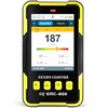
| + | |This is an electronic instrument for detecting and measuring ionizing radiation with the use of a Geiger–Müller tube | ||
| + | |[[File:Geiger measurer.webp|100px|center]] | ||
| + | |Electronic Devices | ||
| + | }} | ||
| + | {{ToolInfo | ||
| + | |Chronos High Speed Camera | ||
| + | |Chronos high-speed cameras are known for their ability to capture video at extremely high frame rates, allowing for slow-motion effects and detailed analysis of fast-moving events. | ||
| + | |[[File:Chronos High Speed camera.jpg|100px|center]] | ||
|Electronic Devices | |Electronic Devices | ||
}} | }} | ||
Latest revision as of 08:46, 14 May 2025
Tools (both hand tools and power tools) are stored at various locations in the Maker Hub. Tools do not require certified training before use, but users are expected to familiarize themselves with tool operation by viewing the appropriate Wiki page. Furthermore, as part of the 'Safety First commandment, users are encouraged to seek help and instruction for any tool that they feel uncomfortable using. Volunteers will be available to serve these needs.
This page contains a list of the tools available in the Maker Hub. Please see the Tool Room page for more information.
| Tool Name | Image | Category | Description |
|---|---|---|---|
| Fume Extractor | Electronic Devices | A device which uses a fan to collect and filter harmful fumes. Always use one of these when soldering for your protection. | |
| Tip Tinner | Electronic Devices | Lead-free tip tinner for soldering. | |
| Analog Discovery 2 | Electronic Devices | A USB oscilloscope, logic analyzer, and multi-function instrument that allows users to measure, visualize, generate, record, and control mixed-signal circuits of all kinds. | |
| Solder Wicks | Electronic Devices | For soldering. | |
| Robin Boards | Electronic Devices | AVR training board used in ENGE320. Coupled with the Atmel 328P Xplained. Shield includes a 7-Segment display, some buttons, a switch, RGB LED's, and a piezo buzzer. | |
| Function Generator | Electronic Devices | A device which can produce a basic electrical signal. Our function generators can produce sine waves, square waves, and triangle waves at frequencies between 1 Hz and 10 MHz. They can also be configured to produce a "sweep signal" - a signal with a linearly varying frequency. | |
| Electronic Scale | Electronic Devices | Device to measure weight or mass. | |
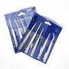
| PCB Tweezers | Electronic Devices | Tweezers for PCBs. | |
| Digilent Nexys 2 | Electronic Devices | A powerful digital system design platform built around a Xilinx Spartan-3E FPGA. | |
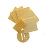
| Solder Station Sponges | Electronic Devices | For cleaning the soldering iron tip. | |
| BTMN Board | Electronic Devices | ARM training board used in ENGE320. Coupled with the Arduino Zero. Shield includes an AMOLED display, joystick, DPAD, RGB LED's, accelerometer, SD Card slot, and a piezo buzzer. | |
| Laser Thermometers | Electronic Devices | Handheld device that can display temperature readout on it after scanning portions of an object or area with the built-in laser. They tend to be inaccurate when measuring shiny objects, putting some non-reflective tape on the object can help give a better measurement. | |
| Multimeter | Electronic Devices | A multimeter is a measuring instrument that can measure multiple electrical properties. A typical multimeter can measure voltage, resistance, and current, in which case can be used as a voltmeter, ammeter, and ohmmeter. Some feature the measurement of additional properties such as temperature and capacitance. | |
| Flux Brush | Electronic Devices | For soldering. | |
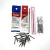
| Solder Tips | Electronic Devices | Replacement tips for soldering irons. | |
| Webcams | Electronic Devices | A video camera which is designed to record or stream to a computer or computer network. | |
| Basys 3 FPGA Board | Electronic Devices | FPGA training board used in ENGE220. Has a bank of switches, buttons, LCD display, 7-Segment display, piezo buzzer, stepper motor driver, and more! | |
| Digital Geiger Measurer | Electronic Devices | This is an electronic instrument for detecting and measuring ionizing radiation with the use of a Geiger–Müller tube | |
| Type K Thermometer | Electronic Devices | A thermocouple for measuring temperatures between -50C and 1300C. | |
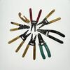
| Wire Strippers | Electronic Devices | For stripping wire. | |
| Arduino Uno | Electronic Devices | Arduino Uno is an open-source microcontroller board based on the Microchip ATmega328P microcontroller. It is a Single circuit board that can be programmed and comprises of 14 digital input/output pins (of which 6 can be used as PWM outputs), 6 analog inputs, a 16 MHz ceramic resonator, a USB connection, a power jack, an ICSP header and a reset button. | |
| Flux Pen | Electronic Devices | For soldering. | |
| Soldering Iron | Electronic Devices | A hand tool which heats metal solder in order to join two components. Soldering is most commonly used to join electrical components in a circuit. There are two soldering kits for use at the electronics station in the center of the Maker Hub, and there are also several available for checkout in the Tool Room. For your safety, please always place the soldering iron in its holder when not in use. Always use a fume extractor to protect yourself from harmful fumes. Soldering kits also come with a tackle box containing useful tools for soldering, such as wire crimpers. Please make sure all contents of this box are returned when you finish using a soldering kit. | |
| Logic Analyzer | Electronic Devices | Used to monitor and debug various digital signals and communication busses. | |
| Heat Sink Clip | Electronic Devices | Heat sink clip for soldering. | |
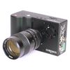
| Chronos High Speed Camera | Electronic Devices | Chronos high-speed cameras are known for their ability to capture video at extremely high frame rates, allowing for slow-motion effects and detailed analysis of fast-moving events. | |
| Digital Tachometer | Electronic Devices | This is an instrument that is used to measure revolutions per minute or RPM. This is a non contact device that uses light and a reflector. This device can be used to measure the RPM of a motor shaft. | |
| Handheld Multimeter | Electronic Devices | An instrument for conducting measurements on a circuit. They can measure DC voltage, AC RMS Voltage, current, resistance, and more. Multimeters are essential tools for testing or troubleshooting a circuit. | |
| DC Power Supply | Electronic Devices | A desktop device to provide DC power to a circuit at a specified voltage. Our BK Precision power supplies have three outputs: two output 0-24 V variable voltage with a max current of .5 A, and one outputs a fixed 5 V with a max current of 4 A. The electronics station in the center of the Maker Hub has several power supplies available for use. If all of these are in use, or if you would like to use a power supply elsewhere in the Hub, you can check one out from the Tool Room. | |
| Flux | Electronic Devices | For soldering. | |
| Helping Hands | Electronic Devices | An extra set of hands to hold things while soldering. | |
| Solder Sucker | Electronic Devices | For sucking solder. | |
| Digital Logic Probes | Electronic Devices | Probes that can be used to analyze the logic states. | |
| A.C. Clampmeter | Electronic Devices | This instrument can be clamped over a wire to measure the current flowing through it. | |
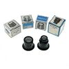
| Eye Loupes | Electronic Devices | Small magnifying glasses. | |
| Oscilloscope | Electronic Devices | An instrument for measuring and graphically displaying varying signal voltages. They can can plot a changing electrical signal over time, and then analyze it for properties including frequency, wavelength, and amplitude. Our oscilloscopes have four channels, meaning they can display four signals at once. | |
| Cordless Drill | Hand Tools | You can use a cordless drill driver to drill or bore holes, drive screws, assemble furniture, and woodworking. | |
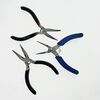
| Needle Nose Pliers | Hand Tools | Skinny pliers. | |
| Torque Wrench | Hand Tools | A torque wrench is a tool used to apply a specific torque to a fastener such as a nut, bolt, or lag screw. | |
| AC/DC Current Clamp | Hand Tools | A current clamp is a device that measures electric current flowing through a wire, cable, busbar, or other conductor. | |
| Snap Ring Pliers | Hand Tools | Used to install or remove snap rings. | |
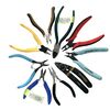
| Clippers | Hand Tools | Also known as diagonal cutters. | |
| Digital Calipers | Hand Tools | Instrument used to gain a precise measurement of a material or structure. | |
| Mirror | Hand Tools | An extendable mirror for viewing hard-to-see places. | |
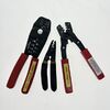
| Crimpers | Hand Tools | For crimping things. | |
| Caulking Gun | Hand Tools | A tool which holds tubes of caulk and is used to seal up cracks and gaps in various structures. | |
| Rivet Gun | Hand Tools | A tool for driving rivets. | |
| Pipe Cutters | Hand Tools | A tool used to cut pipe. | |
| Battery Terminal Cleaner | Hand Tools | A wire brush designed to remove corrosion and contaminants from the terminals of a car battery. | |
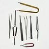
| Tweezers | Hand Tools | Generic tweezers. | |
| Bubble Level | Hand Tools | A bubble level has many uses including, but not limited to verify plumb and level. Some of the many uses include picture and sign hanging, post installation, machine leveling. | |
| Bolt Cutters | Hand Tools | Powerful cutting tool to cut through thick metal pieces. | |
| Impact Driver Kit | Miscellaneous | An impact driver is a tool that is used to drive screws and bolts. It is designed to deliver high torque output with minimal exertion by the user. Impact drivers are ideal for driving large screws and bolts more efficiently than the average compact drill. This set includes various bits that will fit into an impact driver. | |
| Phone Gimbel Set | Miscellaneous | A tool used to stabilize a phone so that it can be rotated around an axis | |
| LED Worklight | Miscellaneous | A really bright light for illuminating an area. | |
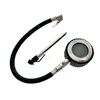
| Pressure Gauges | Miscellaneous | For measuring pressure. | |
| Pressure Regulator | Miscellaneous | This is for reducing the air pressure of a compressed air bottle. | |
| Tarp | Miscellaneous | A big, blue, crinkly tarp. | |
| GoPro Camera | Miscellaneous | For Going Pro. Takes Video and Pictures. Can be used with the GoPro Accessories in the GoPro accessory kit. | |
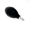
| Helium Balloon Inflator | Miscellaneous | This is connected to a helium bottle and allows the user to fill a helium balloon. | |
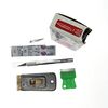
| X-acto Knives and Blades | Miscellaneous | Very sharp. | |
| Fluke Thermal Imager | Miscellaneous | A thermal Camera. Very Expensive. | |
| Bottle Jack | Miscellaneous | This is a hydraulic jack and can be used for lifting heavy objects. Never put anything under heavy objects that you wouldn't want crushed. | |
| Portable Vise | Miscellaneous | A vice grip for holding things. | |
| Socket Wrench Set | Miscellaneous | A socket wrench is a type of spanner that uses a closed socket format, rather than a typical open wrench/spanner to turn a fastener, typically in the form of a nut or bolt. This set comes with an assortment of socket sizes. | |
| Battery Charger | Miscellaneous | This is a battery charger for lead acid batteries. | |
| Heat Gun | Power Tools | A power tool that emits a stream of hot air, usually at temperatures between 100 °C and 550 °C (200-1000 °F), with some hotter models running around 760 °C (1400 °F), which can be held by hand | |
| Dremel | Power Tools | Hand powered tool with different tips, that is mostly used for craft purposes, such as carving, etching and sanding small items. | |
| Cordless 3/8" Impact and Bit Set | Power Tools | The impact Driver is specially designed for tightening and loosening various hex-head bolts, nuts, and lag screws. It employs both rotational force (torque) and short-burst concussive blows (impacts) to deliver an unparalleled amount of power. | |
| Cordless 1/2" Impact Driver and sockets | Power Tools | The impact Driver is specially designed for tightening and loosening various hex-head bolts, nuts, and lag screws. It employs both rotational force (torque) and short-burst concussive blows (impacts) to deliver an unparalleled amount of power. | |
| Cordless Reciprocating Saw 20V | Power Tools | a handheld power saw that features a blade designed to be easily swapped out for different tasks and moves back and forth to quickly cut through a variety of materials. | |
| Holesaw Kit | Power Tools | A holesaw is used in a drill to cut perfectly round holes in a wide variety of materials |


